Plasma-enhanced chemical vapor deposition (PECVD) uses a plasma to generate reactive species from precursor gases. Film-forming reactions can therefore occur under a different thermal budget from a comparable purely thermal CVD process . The result depends on precursor chemistry, plasma exposure and the surface receiving the film. A flow step named only “CVD” or “deposition” does not by itself prove that PECVD was used.
Deposition Film Context in the Flow
The free 40nm flow overview shows the integration roles of a trench liner, trench oxide fill and contact etch-stop deposition. These cross-sections show where films are added and what subsequent steps need from them. Their step labels do not identify a plasma source, so use them as deposition context, not as examples proven to be PECVD.
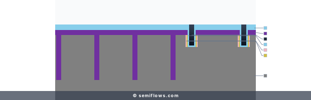
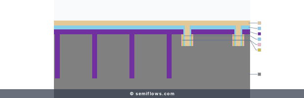
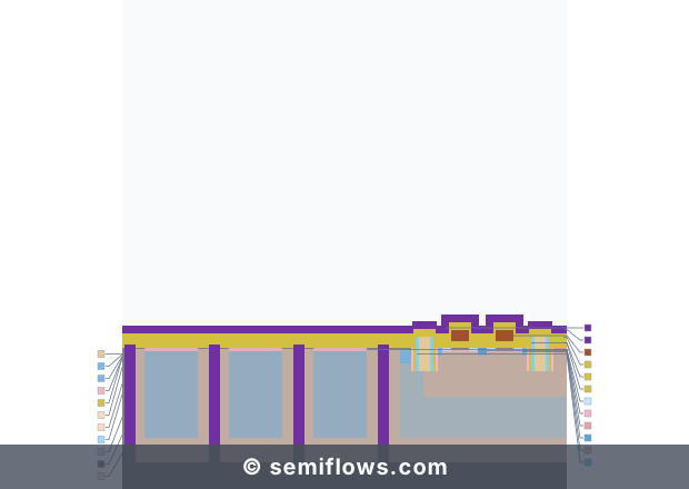
40nm flow cross-sections show deposition roles; the step labels do not establish a PECVD mechanism.
Process map
40nm BSI CMOS Image Sensor
Use the free flow overview to locate liner, fill and etch-stop deposition roles; the step names do not establish PECVD.
Physics & Mechanism
Electrons energized in a discharge can dissociate or excite feed molecules. Reactive neutrals and, depending on reactor design, ions then participate in gas-phase and surface processes that build a solid film. The balance of those processes changes with chemistry, power delivery, pressure, substrate temperature and geometry. In some reactors a sheath accelerates ions toward the surface, affecting density, stress or damage; neither a specific self-bias nor beneficial bombardment is universal. Plasma activation can enable a useful film at a lower substrate temperature, but lower temperature alone does not guarantee a dense, conformal or low-defect film.
Where ICP-PECVD fits: inductively coupled plasma PECVD is one way to energize the plasma used for CVD, alongside capacitively coupled designs. Inductive coupling can supply a dense population of reactive fragments, but the resulting film and surface exposure still depend on the gas chemistry, reactor and wafer conditions. It is a source design within PECVD, not a separate deposition family or a guarantee of better coverage. A PECVD methods review distinguishes the two coupling types; the 40nm flow labels above identify neither one.
Process Principles
- Chemistry and thermal budget: precursor and reactant choices determine the possible network; plasma activation changes the energy available to reactions. Compare a process with its actual material and surface requirements, not a generic “plasma versus furnace” claim.
- Growth and coverage: transport into a recessed feature and reaction at its surfaces jointly determine coverage. More reactive fragments can increase growth rate yet also deplete species near an opening.
- Film quality and exposure: power, ion flux and surface temperature can affect hydrogen content, stress and interface damage. Their direction and magnitude depend on the chosen chemistry and reactor.
- Downstream fit: a liner, gap-fill dielectric or etch-stop layer must meet different isolation, coverage and etch-selectivity needs.
Challenges & Failure Modes
Hydrogen or other precursor fragments may remain in some films, with composition and subsequent heat exposure affecting stability. Ion and photon exposure can alter sensitive interfaces or charge dielectric stacks. Gas-phase reactions may create particles, and aggressive ion bombardment may roughen or resputter a growing layer. None of these outcomes follows from the word PECVD alone; the film and interface have to be measured.
From Principle to Production Flow
Use the 40nm overview to trace the order in which a liner, fill and stop layer are introduced. The illustrations do not disclose the exact deposition technique at those stations. For the wider process family, read deposition and CVD. A process name, cross-section and final film property answer different questions.
Technology Node Evolution
Denser features and temperature-sensitive stacks increase the value of controlling film growth without relying only on substrate heating. They also make coverage and plasma exposure more consequential. Different materials and geometries call for different deposition methods; PECVD is one option, rather than an automatic answer for every trench, fin or hard mask.
Related Processes
Atomic layer deposition can provide highly controlled cyclic growth where surface reactions permit it. LPCVD uses a different reaction regime. Silicon dioxide, amorphous carbon and etch-stop layers describe film roles or materials, not proof of a particular plasma process.
Future Outlook
The integration question remains how to deliver the needed film and interface properties while limiting heat, charging, damage and poor coverage. Compare measured results for the intended structure before assigning a deposition route.
References
Silicon VLSI Technology - Full
James D. Plummer, Michael D. Deal, Peter B. Griffin
Silicon VLSI Technology · ISBN 978-0130850379