Temperature influences many semiconductor processes, including diffusion, reaction kinetics, film stress, and equipment behavior. Some thermally activated rates approximately follow Arrhenius behavior over a defined range, while other effects do not. Time and temperature together contribute to a thermal budget, whose practical limit depends on the materials already present. This article traces those interactions rather than assigning one universal temperature law to every step.
Where Temperature Acts in the Flow
The 40nm BSI CMOS Image Sensor flow shows three distinct thermal duties with flow cross-section schematics, all publicly visible:
- Thermal growth: a sacrificial oxidation uses heat to make silicon and oxidant react — temperature setting both the growth rate and the interface quality that survives into the gate stack.
- Grain stabilization: a polysilicon anneal holds the deposited film at temperature long enough for its microstructure to settle into the form the gate needs.
- Dopant activation: a dopants activation step repairs implant damage and moves dopants onto lattice sites — a thermal operation whose conditions depend on the device and sequence.
Each step is publicly visible with its flow schematic from the 40nm flow overview; the flow is free.
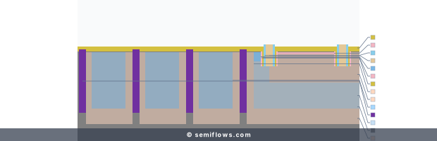
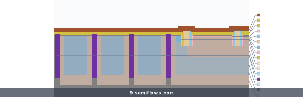
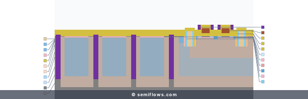
The free 40nm flow shows separate thermal operations; cross-sections do not report temperature histories.
Process checkpoint
Understand Dopants Activation in context
Inspect a dopant-activation thermal duty; the step label does not establish its peak temperature.
Process context for “Process Temperature and Thermal Budget”: 40nm BSI CMOS Image Sensor · PCN · Step 104
Physics & Mechanism
For a process governed by one dominant thermally activated mechanism over a defined range, an Arrhenius relation can describe how a rate changes with temperature . Diffusion, reaction, and relaxation may have different activation energies; phase changes, transport limits, and equipment effects need their own models. A change in temperature therefore cannot be assigned one universal rate multiplier or selectivity outcome.
A thermal budget describes a sequence of time–temperature exposures relative to a specified material or device limit. It is not generally a sum of degree-seconds: effects with different activation energies require different weighting, and ramp times may matter. A later heat step can affect structures already present, so integration checks the response of junctions, interfaces, and interconnect materials individually . High-temperature operations often precede heat-sensitive materials, but the maximum allowed temperature need not fall monotonically at every step.
Rapid thermal processing shortens exposure compared with a furnace cycle. Localized laser heating can further confine energy, but the depth and lateral extent depend on optical, thermal, and material properties. A study modeling laser-induced silicidation of 4H-SiC contacts illustrates this specific case and its thermal-stress considerations . It does not prove that a silicon wafer bulk stays cold or that all laser steps avoid damage.
Process Principles
- Define the material limit: a useful budget states which structure and measured property it protects.
- Use the complete time–temperature history: peak temperature alone omits ramp and hold effects; one scalar budget does not cover every mechanism.
- Check integration order: earlier junctions and interfaces may respond to later heat, while some steps require different thermal windows.
- Measure uniformity: temperature distribution can affect outcomes alongside gas delivery, geometry, and other process variables.
- Treat local heating as a specific technique: its benefits and stress risks depend on absorption, heat flow, and the stack.
Challenges & Failure Modes
- Junction movement: activation and dopant diffusion can compete; a profile measurement is needed to establish the outcome.
- Interface change: later heat may alter an existing interface, depending on materials and ambient.
- Thermal stress: gradients and expansion mismatch can bend or damage a wafer or film stack.
- Interconnect limits: metals, barriers, and dielectrics impose material-specific constraints rather than one universal ceiling .
From Principle to Production Flow
The free 40nm flow overview identifies oxidation, polysilicon annealing, and dopant activation as distinct thermal operations. The figures show their process context, not temperature traces or comparative thermal budgets. Related explanations include annealing, rapid thermal annealing, oxidation, and back end of line.
Technology Node Evolution
Shorter exposures and localized heating can help when a device stack has little margin for additional heat. Their value must be established for each material system. The 4H-SiC laser-silicidation model is an example of contact-specific analysis; it is not a general recipe or a silicon-node trend.
Related Processes
Annealing, rapid thermal annealing, oxidation, front end of line, and silicon carbide illustrate different thermal constraints. Their process windows should not be combined into one temperature limit.
Future Outlook
More selective heat delivery and better coupled thermal, mechanical, and electrical measurements may reduce unwanted exposure. The aim is to validate the desired reaction and the response of neighboring structures for a specific stack.
References
Temperature and Stress Simulation of 4H-SiC during Laser-Induced Silicidation for Ohmic Contact Generation
B. Adelmann, R. Hellmann
Silicon VLSI Technology - Full
James D. Plummer, Michael D. Deal, Peter B. Griffin
Silicon VLSI Technology · ISBN 978-0130850379
Physics of Semiconductor Devices - Full
S. M. Sze, Kwok K. Ng
Physics of Semiconductor Devices · ISBN 978-0-471-14323-9