The front end of line (FEOL) is the first half of chip fabrication — the portion where transistors (and other active devices) are built directly in the semiconductor substrate: isolation structures that prevent crosstalk, wells that set the device body, gate stacks that govern switching, junction implants, source/drain regions, and the silicides that contact them. By architectural convention it covers every step up to, but not including, the first metal interconnect deposition. FEOL defines the chip's electrically active regions and sets the ultimate drive current, leakage, and reliability floor of the whole product; everything after it just wires the devices together.
The Four Milestones of FEOL
Walk any logic flow from bare wafer to finished transistors and four structural milestones repeat in order — each one a module of real steps:
- Isolation: the active areas are defined and the gaps between them are trenched, filled with dielectric, and planarized — today, shallow trench isolation (STI); historically, local oxidation (LOCOS), abandoned when its "bird's beak" oxide encroachment and tall field-oxide steps blocked further spacing and focus budgets.
- Gate stack: the thin gate dielectric and the gate electrode are formed over the channel — the structure that switches the device.
- Junctions: extension and threshold implants place dopant atoms at controlled depths around the gate, setting the channel's electrical character.
- Source/drain: raised or embedded source/drain regions are grown or implanted, and silicide contacts formed, completing the transistor as a device you can drive current through.
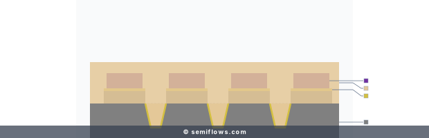
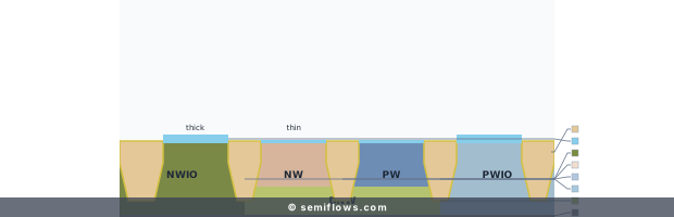
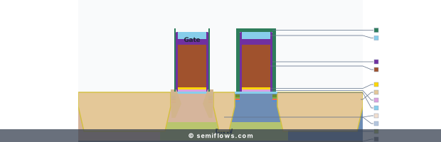
Real cross-sections rendered by the same engine as the 28nm planar course — step names, layer-by-layer rationale, and the full sequence unlock inside the course.
Process map
A selected 4-step learning trail in 28nm Planar Flow
Milestone 1 — isolation: the oxide fill that seals the trenched gaps between device regions.
Real step names, layer-by-layer cross-sections, and rationale live inside the 28nm Planar Flow course, unlocked by account access.
Physics & Mechanism
FEOL engineering is applied band theory. In the silicon crystal, electrons move not freely but modulated by the periodic lattice potential, which forms the energy bands and the bandgap (Bloch's theorem). Building a transistor means deliberately breaking that uniformity where a device is needed: dopant atoms introduced by ion implantation substitute into the lattice and add localized states in the bandgap, their spatial profiles roughly Gaussian in depth, set by implant energy, dose, and stopping power.
Device operation then rests on electrostatics: the gate field bends the silicon bands across a thin dielectric until the surface inverts, creating a conducting path between source and drain. The quality of that modulation is set by the silicon/dielectric interface — structural and chemical defects there become trap states that degrade mobility and gate control, which is why interface passivation runs through the entire FEOL narrative.
Process Principles
- Lithography + etch co-optimization: the Rayleigh criterion (CD ∝ λ/NA) bounds every FEOL dimension; transferring the printed pattern demands directional dry etching whose profiles must track the lithographic intent.
- Thermal budget management: anneals must activate implanted dopants (repairing damage, driving atoms into substitutional sites) yet not diffuse them deeper — Fick's laws have no off switch — so activation and ultra-shallow junctions are the same negotiation, with low thermal budgets suppressing lateral and vertical diffusion at the cost of careful defect-recovery work.
- Gate-stack materials: high-k metal gate stacks with atomic layer deposition dielectrics scale equivalent oxide thickness without tunneling leakage — capacitance up, leakage flat.
- Planarization discipline: chemical mechanical planarization and its cleaning modules recur across FEOL (STI, dielectric stacks) because every subsequent lithography layer needs a flat, focused surface.
Challenges & Failure Modes
- The thermodynamic wall: subthreshold swing has a room-temperature floor set by Fermi-Dirac carrier statistics; as scaling approached the 32nm-era limits, static power crept up relative to dynamic power — leakage, not switching, became the power problem.
- CMP pattern-density effects: removal rate depends on local layout density — dense arrays erode, isolated features dish — degrading across-chip uniformity right where subsequent HKMG integration needs precision.
- Interface reliability: low-temperature budgets that preserve sharp dopant profiles can leave dangling bonds incompletely passivated; the resulting interface states trap carriers, shifting threshold voltages, raising random telegraph noise, and feeding long-term bias temperature instability.
From Principle to Production Flow
The four milestones above are exactly how a real flow is laid out. In the 28nm planar flow, the active-area module patterns and etches the isolation trenches; the gate module grows the gate dielectric and deposits the gate stack; the implant modules place the extension and threshold doses; the source/drain module etches, fills with selective epitaxy, and hands off to silicide. The named step sequence, each milestone's cross-section, and the layer-by-layer rationale are part of the paid course — start from the 28nm planar flow overview to walk the front end module by module.
Technology Node Evolution
At planar nodes like 28nm, the industry boosted mobility with strained-silicon engineering rather than structural change. As gate lengths shrank and planar electrostatics failed, the 14nm node brought the fin field effect transistor (FinFET): wrapping the gate around three sides of a vertical fin restored capacitive control, suppressed subthreshold leakage, and re-enabled voltage scaling. By the 7nm node and beyond, even fins showed electrostatic limits, and FEOL evolved toward gate-all-around (GAA) nanosheets, with multi-height standard cells co-optimizing power, performance, and area while managing parasitic coupling.
Related Processes
FEOL hands off to the middle-of-line (MOL) and the back end of line (BEOL): silicide contacts on source/drain form the junction between realms, and as BEOL copper dimensions shrink, thin diffusion barriers keep BEOL metal from drifting into FEOL active silicon. The planar integrity established during FEOL CMP directly conditions MOL and BEOL yield.
Future Outlook
The FEOL/BEOL boundary itself is blurring: backside power delivery networks (BSPDN) route power distribution through the wafer backside, decoupling power rails from signal routing and minimizing IR drop. At the research frontier, scanning-tunneling-microscope hydrogen-desorption lithography positions dopants atom by atom — beyond solid-solubility limits — pointing at the ultimate FEOL trajectory: sculpting the channel one atom at a time.
References
Physical and technological limitations of NanoCMOS devices to the end of the roadmap and beyond
S. Deleonibus · The European Physical Journal Applied Physics