Deep ultraviolet (DUV) is the workhorse exposure band of semiconductor lithography: the spectral lines of KrF and ArF excimer lasers — shorter than the near-UV mercury lines (g-line/i-line), and therefore capable of printing smaller critical dimensions by the Rayleigh criterion. It is the core light source of modern photolithography and simultaneously the operating band of wide-bandgap emitters and detectors. The key to understanding DUV in production is to see it as the start of a chain: DUV exposure writes the mask's pattern into the photoresist as a latent image, development turns it into a physical mask, and plasma etch transfers the pattern into the layer below — a three-leg relay that fails if any leg is missing.
Expose, Develop, Transfer: One Complete Chain
A patterning module in production is always the same chain: a pre-exposure clean prepares the surface, DUV exposure writes the latent image, etch converts it into a real structure, and a strip/clean closes the module. DUV owns the critical "write" leg.
- Pre-litho clean: particles and residue off, so resist coats uniformly and focus holds.
- DUV exposure: projection optics image the reticle into the resist at DUV wavelength — pitch set by wavelength and numerical aperture.
- Etch transfer: the developed resist profile serves as the mask while anisotropic plasma etch copies the pattern into the layer below.
- Strip and clean: ashing and wet cleaning remove the resist, handing a clean structure to the next module.
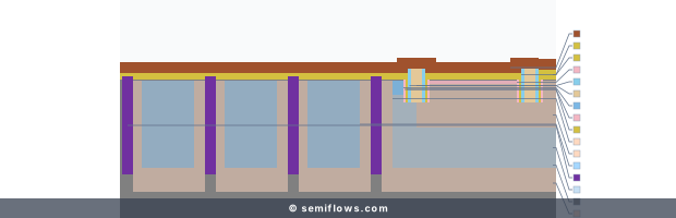
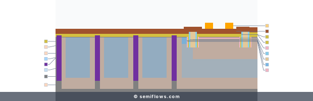
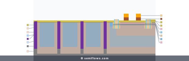
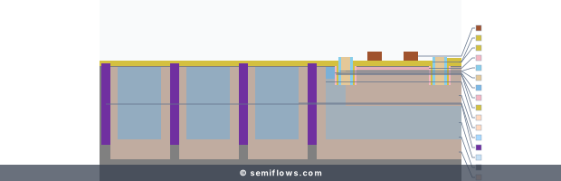
Real cross-sections from the free 40nm flow — the same steps this article's learning route links to.
Process checkpoint
Understand Pre Litho Cleaning in context
See the surface preparation that makes uniform coating and reliable focus possible before exposure.
Process context for “DUV: From Exposure to Pattern Transfer”: 40nm BSI CMOS Image Sensor · GATE · Step 81
Physics & Mechanism
Diffraction Sets Resolution
The minimum resolvable feature obeys CD ∝ λ / NA: shorter wavelength, larger numerical aperture, finer pitch. Pushing the exposure wavelength into the DUV band was the physical necessity of scaling. But shorter-wavelength photons carry more energy, and the photoactive compounds of g-line/i-line resins absorb them violently at the top of the film — the direct reason resist chemistry had to change. Optical lithography modeling pairs Fourier optics (describing the projection tool) with resist chemistry (describing image formation in the polymer film) .
Chemically Amplified Resists
DUV lithography depends on photoresist formulations containing photoacid generators: a PAG absorbs a DUV photon and photolyzes to release a local catalytic acid; during post-exposure bake, thermal energy drives acid diffusion along the polymer backbone, catalyzing a cascade of deprotection reactions that switch local solubility. One acid proton catalyzes many events before being quenched — the "amplification" that compensated for early DUV sources' photon flux. The balance among acid generation yield, diffusion length, and boundary neutralization kinetics sets the latent-image slope and the final line-edge roughness.
DUV Optoelectronics
Emitting or detecting DUV requires wide-bandgap materials (AlGaN, diamond): DUV photons are absorbed within a very shallow surface layer, so surface-state passivation is decisive for suppressing non-radiative recombination. DUV LEDs use sub-wavelength surface photonic structures to break total internal reflection and widen the escape cone; backside-illuminated DUV sensors use low-temperature ALD to passivate dangling bonds on the back surface.
Process Principles
- Resolution vs. depth of focus: the flip side of CD ∝ λ/NA is DOF ∝ λ/NA² — trading NA for resolution collapses the focus budget; when substrate topography exceeds it, images distort, lines thin, and neighbors bridge, which is why CMP planarization precedes critical lithography.
- Reflection control: reflective underlayers create standing waves and interference inside the resist; a bottom anti-reflective coating (BARC) absorbs the penetrating light and suppresses the reflections, eliminating local linewidth swings and notching.
- Mask-to-etch selectivity: DUV resists chemically degrade under high-density plasma, so etch recipes balance chemistry, ion energy, and surface passivation to preserve polymer-mask selectivity during transfer.
Challenges & Failure Modes
- Airborne molecular contamination (AMC): chemically amplified resists are acutely sensitive to cleanroom bases (ammonia, amines, NMP) — molecules adsorbed between exposure and bake neutralize surface acid, yielding insoluble "T-topped" profiles, scumming in unexposed trenches, and wafer-level CD drift.
- Focus budget vs. topography: a high-NA lens's shallow depth of focus meeting unplanarized topography leaves parts of the field out of focus — distortion, thinning, bridging.
- Material damage and contact degradation: high-energy photons can break bonds and seed defect centers in 2D materials and ultrathin interfaces ; wide-bandgap contacts additionally suffer Fermi-level pinning and Schottky-barrier degradation, forcing a joint balance of exposure energy, thermal budget, and refractory metallization.
From Principle to Production Flow
The "clean → expose → etch → strip" chain appears in production as adjacent, named steps. The gate module of the 40nm BSI CMOS Image Sensor flow is a complete example: after the pre-lithography clean, a KrF excimer exposure defines the gate pattern, the polysilicon etch transfers it into the gate electrode, and ashing with wet cleaning closes the module. From the 40nm flow overview you can walk the chain with real cross-sections — a free course flow, so step names, section states, and explanations are publicly visible.
Technology Node Evolution
In the planar era (28nm planar process, 28nm gate patterning), dry ArF DUV single-exposure resolved the critical layers; immersion lithography then filled the lens-wafer gap with high-purity water, pushing numerical aperture past 1.0 and pitch finer still. At 14nm FinFET and beyond, pitch fell below the immersion single-exposure limit, and multipatterning — SADP, LELE — extended DUV's lifetime at the cost of accumulating overlay error, process complexity, and edge-placement error, ultimately driving the most demanding layers to extreme ultraviolet (EUV) lithography.
Related Processes
DUV patterning is bracketed by its neighbors: the resist and BARC form the coating stack (photoresist); development relies on TMAH chemistry (tetramethylammonium hydroxide); pattern transfer belongs to dry etching; and in the multipatterning era, SADP/SAQP spacer schemes (see self-aligned double patterning) treat the DUV exposure as a coarse-pitch input and subdivide it further with deposition and etch.
Future Outlook
DUV and EUV will coexist for a long time: EUV owns the densest layers of the most advanced nodes while immersion DUV with multipatterning carries the vast majority of the rest, buffering capacity and cost through the High-NA EUV transition. On the optoelectronic side, higher-power DUV LEDs and solar-blind detectors keep advancing with wide-bandgap epitaxy and passivation progress.
References
Patterning metal contacts on monolayer MoS2 with vanishing Schottky barriers using thermal nanolithography
Xiaorui Zheng, A. Calò, E. Albisetti, Xiangyu Liu, Abdullah Alharbi, Ghidewon Arefe et al. · Nature Electronics
Silicon VLSI Technology - Full
James D. Plummer, Michael D. Deal, Peter B. Griffin
Silicon VLSI Technology · ISBN 978-0130850379